Designing in Fulcrum One
To start adding items to a new project in Fulcrum One, make sure you've selected the Design workspace using the tab at the top of the window.

Adding a 3D venue model
We'll start our new project by importing a 3D model of the room into the software. Start by selecting the Modeling toolbox by clicking the  tab on the left side of the screen. If your project is empty, you will be prompted to import a model. If not, you can always click the + beside the Objects list to add a new model to your project.
 tab on the left side of the screen. If your project is empty, you will be prompted to import a model. If not, you can always click the + beside the Objects list to add a new model to your project.
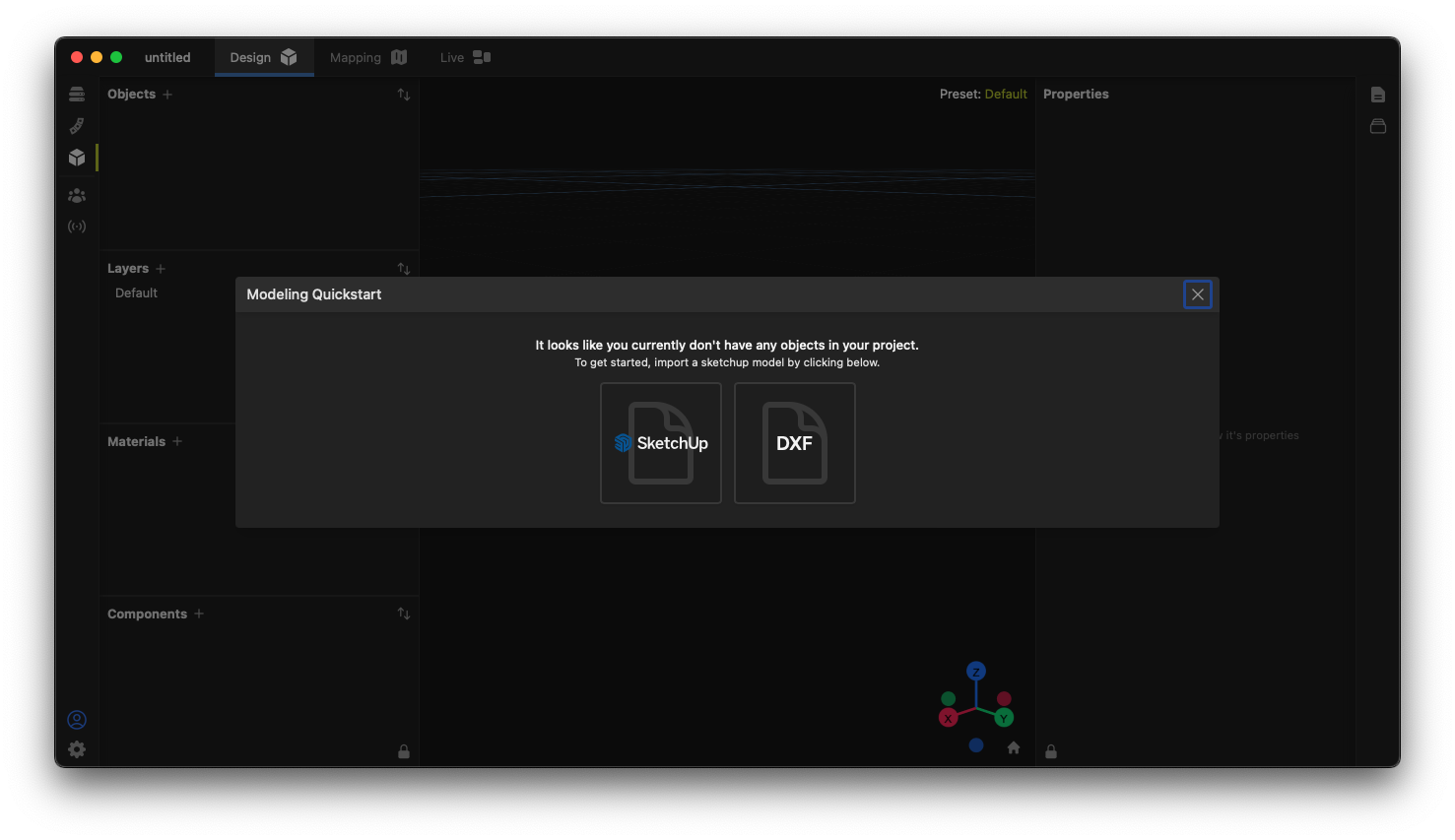
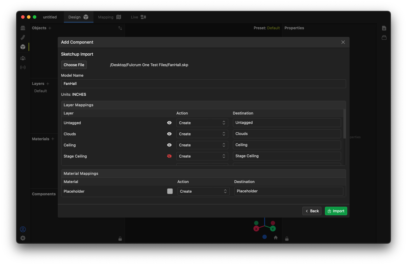
At this time, Fulcrum One supports the loading of 3D models from the Sketchup application using a ".skp" file or generic 3D CAD models using a DXF file. See the support article "Creating Venue Models" for more information and tips on creating models compatible with Fulcrum One and "Import and Export Formats" for more information on file formats.
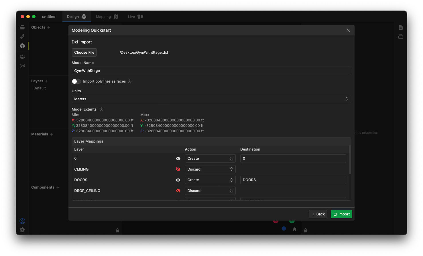
The Add Object dialog boxes are shown below for both Sketchup and DXF files. Select the desired import format and then click the Choose File button to select a file from your computer to use. Using this dialog, you can rename the model, create links to new or existing layers in your file, and map materials from the file into the model. For DXF files, you can also select the file measurement units as well as elect to convert polylines to faces. For now, we will leave these options as default.

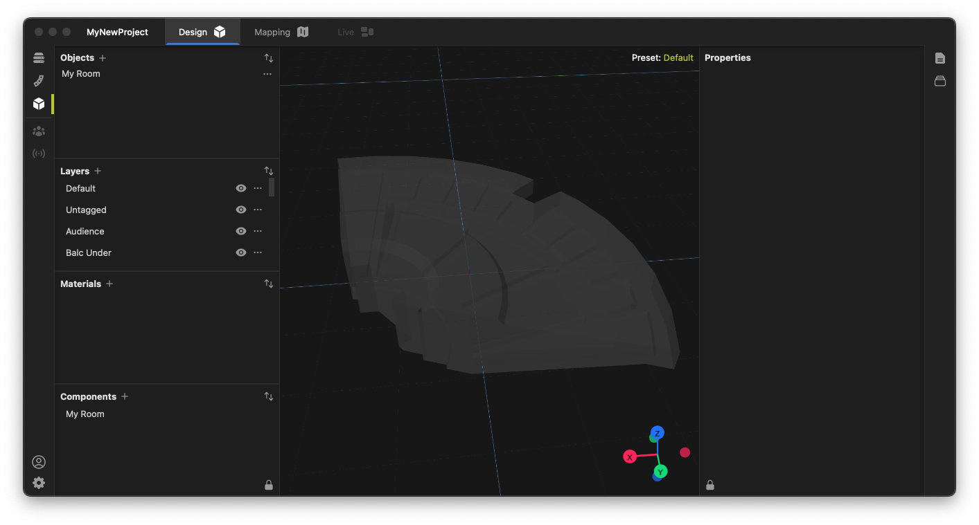
Once you confirm all options, the model file will be shown in the Design window.
Note that Objects (representations of a 3D model) may be moved or rotated as they are placed. However, we recommend following Fulcrum One's modeling standards for ease of use if possible.
Navigating the model
Mouse and keyboard combinations
The 3D world inside One can be easily navigated with a few simple mouse and keyboard combinations.
| Rotate around current viewport | Hold center mouse button and drag or Click and drag with left mouse button away from the model |
| Zoom in and out | Roll center mouse wheel or Pinch trackpad |
| Pan the viewport | Hold center mouse button with shift key and drag or While holding shift key, click and drag with left mouse button away from the model |
3D Gizmo control
The 3D world can also be easily navigated by clicking, dragging or selecting points on the 3D Gizmo display in the bottom left corner of the viewport.


Selecting and editing items
Individual items, like models, surfaces or loudspeaker can be easily selected using the left mouse button inside the model viewport. When selecting an item, click the Properties toolbox  on the right to see controls available to edit that item.
 on the right to see controls available to edit that item.
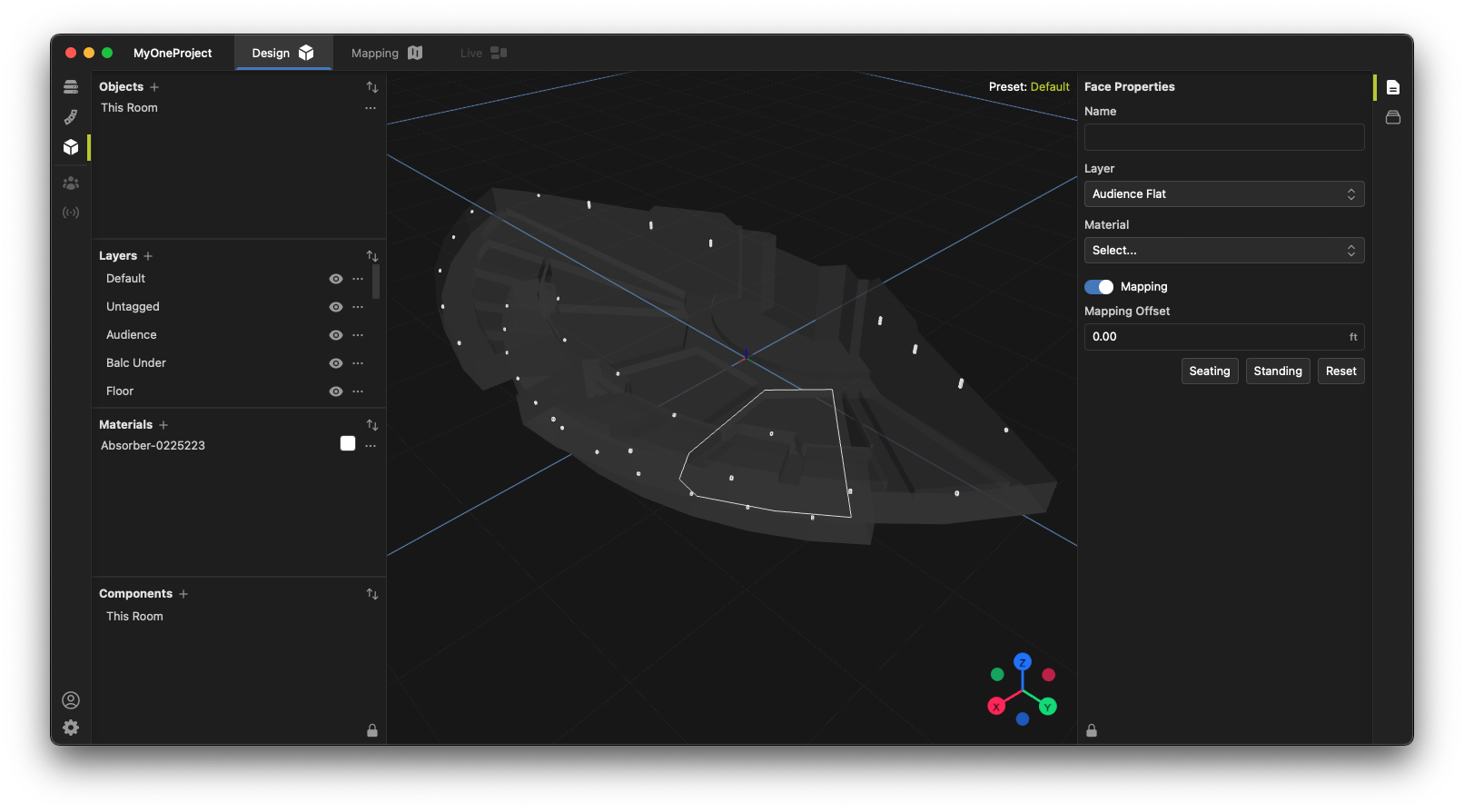
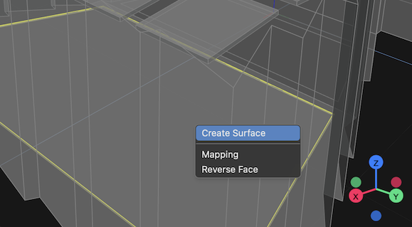
Note that some items (such as loudspeakers) also have a context menu available providing other options, accessible by right clicking the item in the 3D view. For example, when right clicking a face in the model, you have the option to create a mixing surface, enable mapping or reverse the face orientation.
Adding loudspeakers
You can add loudspeakers to your model by selecting the loudspeakers  toolbox on the left side of the window and clicking the + button. Click the Loudspeaker drop down option to add a single loudspeaker to your project. This opens the Speaker Library window.
 toolbox on the left side of the window and clicking the + button. Click the Loudspeaker drop down option to add a single loudspeaker to your project. This opens the Speaker Library window.
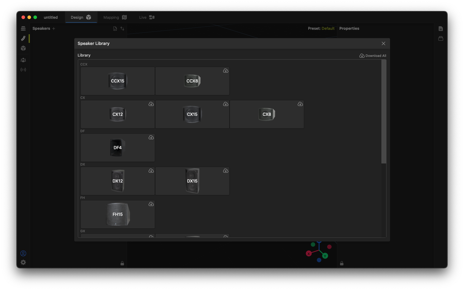
You can choose loudspeakers from the families listed in this window, then select the variant or horn pattern you wish to use in your model. If a specific loudspeaker family has not been downloaded, a  icon will appear. You can then either:
 icon will appear. You can then either:
- Click the icon beside the loudspeaker to download the modeling data for that loudspeaker alone, or
- Click the
 icon at the top of the window to download all loudspeaker data available. Note this may take an extended amount of time but can be helpful, especially if you might be using the program away from a reliable internet connection.
 icon at the top of the window to download all loudspeaker data available. Note this may take an extended amount of time but can be helpful, especially if you might be using the program away from a reliable internet connection.
Positioning and aiming
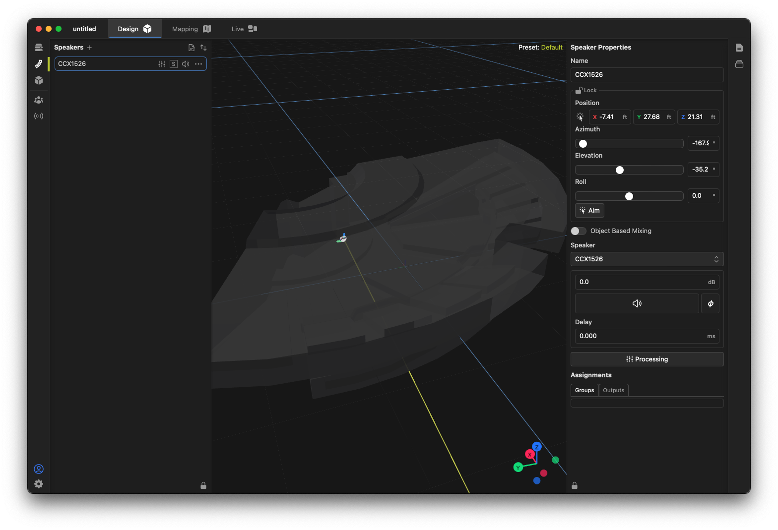
One the loudspeaker has been selected, it will be added to your model at the model origin. At this point, there are multiple ways to position and aim the loudspeaker in your model. First, select the loudspeaker by clicking it in either the 3D viewport or by selecting it in the Speakers toolbox list. The Properties toolbox will now show the physical position and orientation of the loudspeaker, which can be directly edited.
In addition to the properties box, a selected loudspeaker has handles in the 3D view allowing it to be interactively moved around the model. Note that, if the speaker is Locked using the  control, these handles will not be available to prevent accidental movements.
 control, these handles will not be available to prevent accidental movements.
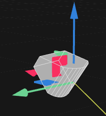
Accelerated positioning and aiming
Loudspeakers can be directly positioned on surfaces by clicking the  button in the Properties toolbox and then clicking on a surface in the model.
 button in the Properties toolbox and then clicking on a surface in the model.
Similarly, loudspeakers can be quickly aimed at a specific point by clicking the  button in the Properties toolbox and then clicking on a target surface in the model.
 button in the Properties toolbox and then clicking on a target surface in the model.
Duplication, mirroring and other controls
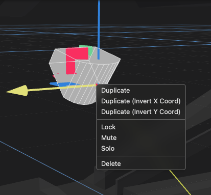
A context menu is available for loudspeakers by right-clicking the loudspeaker in the 3D view or in the toolbox list. This allows you to easily duplicate a loudspeaker while keeping all settings and properties in place. In addition, you can duplicate a loudspeaker and invert its X or Y coordinates, which can greatly speed the creation of symmetrical pairs of loudspeakers. Other controls are also available in the context menu for accelerating the design process.
Group assignment
For ease of modeling and control of larger systems, Fulcrum One allows the use of Groups to organize the control of various speakers in one location. Create groups using the  Toolbox on the right side of the screen. Groups can have individual mute, solo and equalization settings, and groups can be overlaid, meaning a loudspeaker can be a part of multiple groups at one time.
 Toolbox on the right side of the screen. Groups can have individual mute, solo and equalization settings, and groups can be overlaid, meaning a loudspeaker can be a part of multiple groups at one time.
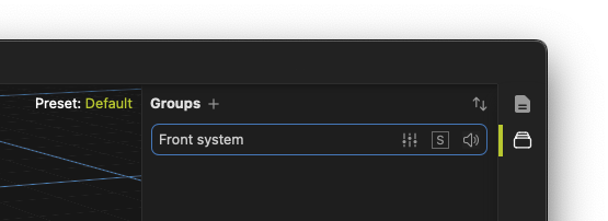
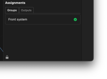
Speakers may be assigned to groups from the speaker Properties toolbox when that speaker is selected. Use the list at the bottom and click the groups you wish for that speaker to join.
The speaker report
A complete Speaker Report view of all loudspeakers in the project may be obtained by clicking the  icon in the Speakers toolbox.
 icon in the Speakers toolbox.
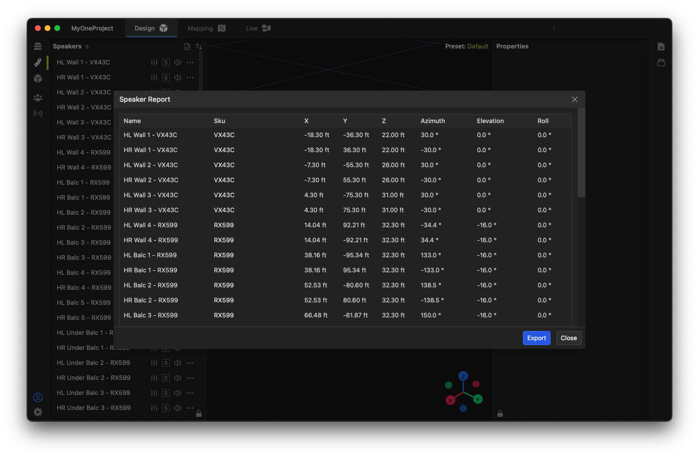
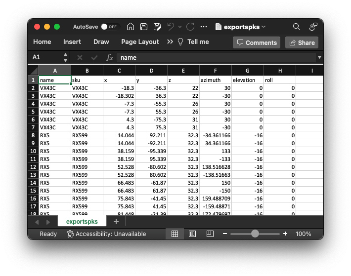
The Speaker Report window shows the naming, position and orientation of each loudspeaker in the project. Values may be directly edited in the report view, and the Export button can be used to create a comma-separated text file ".csv" of the data for use in other programs.
Loudspeaker arrays
Loudspeaker arrays may be added with compatible products by selecting the loudspeakers toolbox on the left side of the window and clicking the + button. Click the Array drop down option to add a loudspeaker array to the project. This opens the Speaker Library window, showing only loudspeaker compatible with the array function.
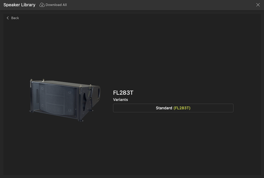
Choose a compatible array loudspeaker to start the array, then choose the variant of that loudspeaker on the next page, such as the FL283T in the following example:
You will then be asked to confirm the quantity of loudspeaker boxes to add to the new array:

Array properties
Once a new array has been added to the project, you will see the array listed in the Loudspeakers list. Expanding the array in the list will show the individual "member" boxes inside that array. Note that processing, mutes and solos may be accessed for the entire array as a whole, or for each individual member to assist with design and configuration.
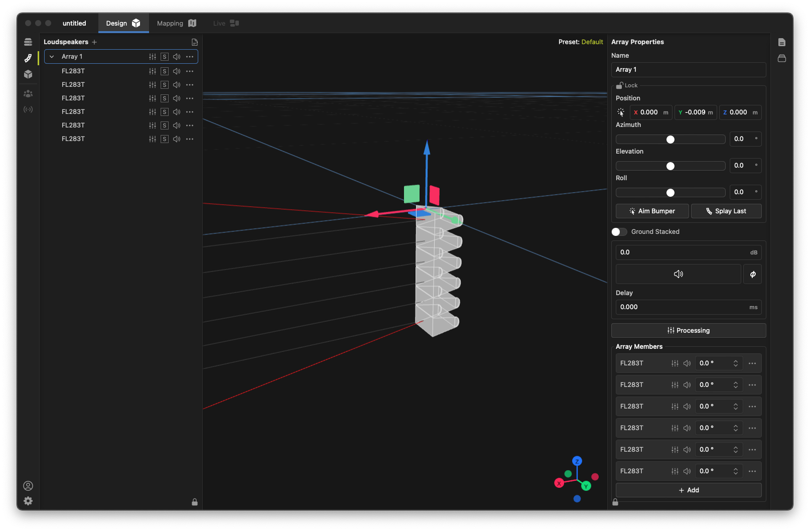
Open the Properties toolbox and select an array in either the Loudspeakers list or in the 3D view. The Array Properties toolbox shows controls necessary to position, aim and process the array, including:
- Naming, positioning, and overall aiming controls (similar to that of a single loudspeaker box),
- Aim Bumper and Splay Last controls (more below),
- Ground Stacked option (more below),
- Level, mute, delay and processing controls (similar to that of a single loudspeaker box),
- Array Members list for configuration of each member box.
When an array is selected, the 3D view will show positioning controls, the centerline of each member box, and the upper and lower theoretical coverage limits for the current array configuration.
By default the Ground Stacked option is disabled, meaning the array is configured for typical suspended operation, with the first member box being the uppermost box. When Ground Stack is enabled, the array is configured for conditions where the system is "sitting" on a floor surface, with the first member box reflecting the lowest box in the array.
Aiming a line array
Fulcrum One contains some shortcuts to quickly aim and splay a line array to match the geometry of a room. Follow these basic steps to quickly aim a suspended line array (the process is similar for a ground-stacked array):
- Add the desired number of array member boxes and position the array at the desired location in the room.
- You must enable mapping on any audience surfaces that the array will be expected to cover along its axis. Use the
 control to enable model surfaces for mapping if they are not already enabled.
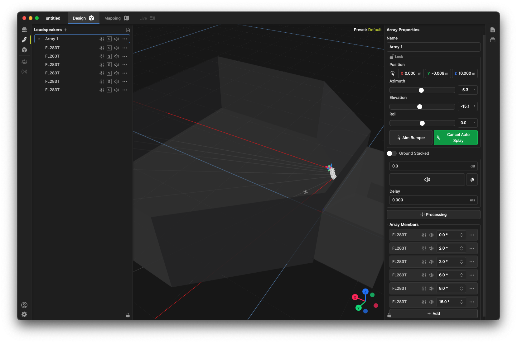
 - Select the array and click the Aim Bumper button. Then, click the point in the coverage area where you want to aim the topmost box of the array (typically the furthest point in the audience area). The array will tilt and align to aim at this point.
 control to enable model surfaces for mapping if they are not already enabled.
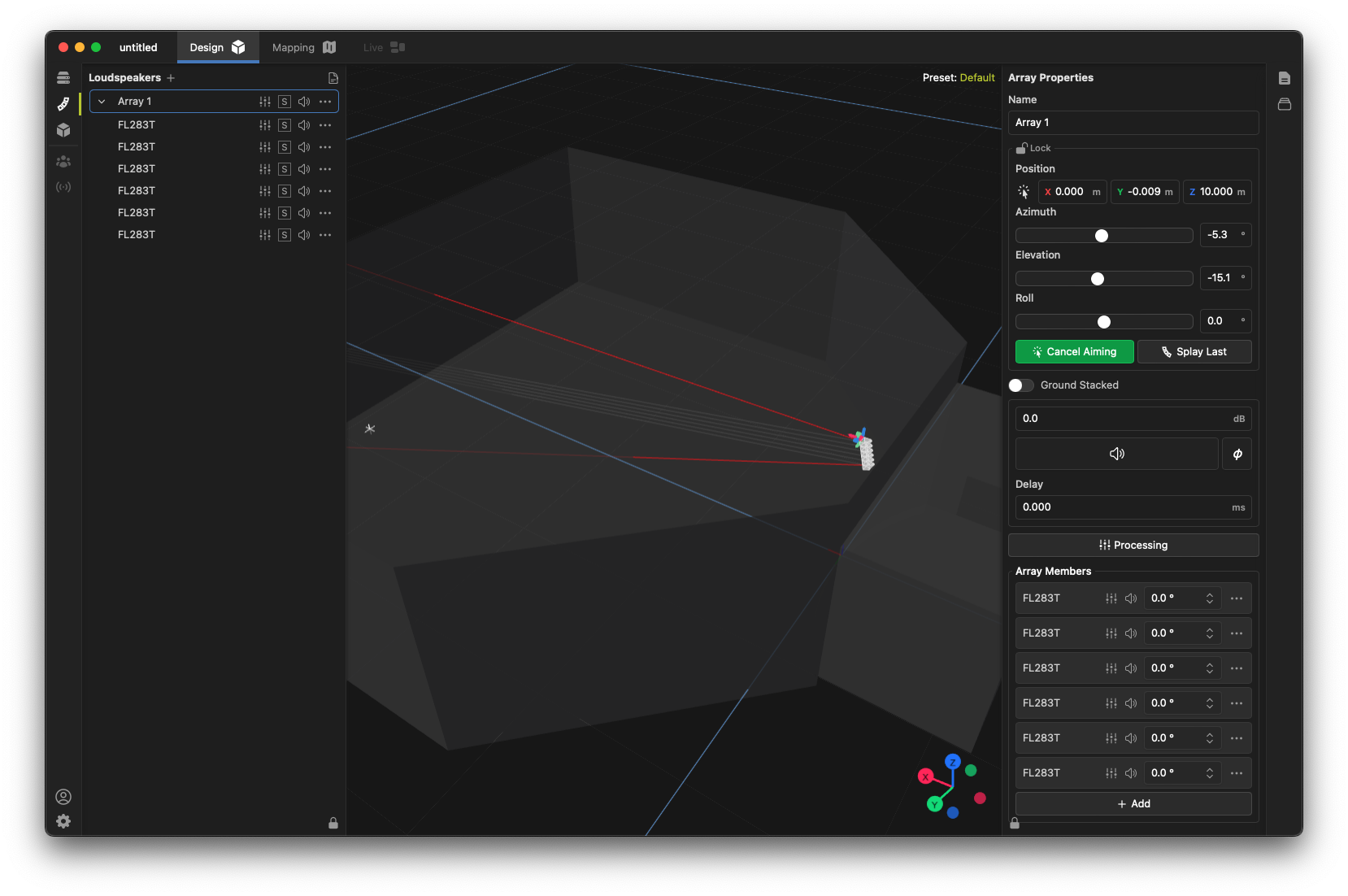
- Next, click the Splay Last button and select the point in the coverage area where you ideally want to aim the bottom box of the line array (typically the closest point in the audience area). The array will "splay" to attempt to cover this area, and box-to-box splay angles will be adjusted in the Array Members list accordingly.
The process of aiming a ground-stacked array is similar, except that the Aim Bumper aiming typically points to the closest desired audience position, and the Splay Last aiming points to the furthest position.
Array optimization
Fulcrum One includes the ability to automatically optimize the coverage and voicing of loudspeaker arrays when coupled with Driveflex power amplifiers. Optimizations may be computed either online or during the design phase, and the results are instantaneously synchronized to Driveflex amplifiers when connected. Currently, CC, FL, and AHS arrays may be optimized.
We recommend you start with a basic physical aiming of the array using the Aim Bumper and Splay Last functions above, then use the optimization function to refine the design once the physical aiming is complete. Optimization can perform two functions:
- Coverage optimization: attempts to smooth the coverage of the array to be more consistent across the intended listening area. Fulcrum's coverage optimization algorithm addresses both low-frequency and high frequency coverage using beam forming and wave shaping techniques to achieve the desired results.
- Voicing: attempts to adjust the tonal balance of the array to achieve a desired target curve across the listening area.
For CC and FL arrays, you may choose to perform either optimization function alone or both at the same time.
Performing an optimization
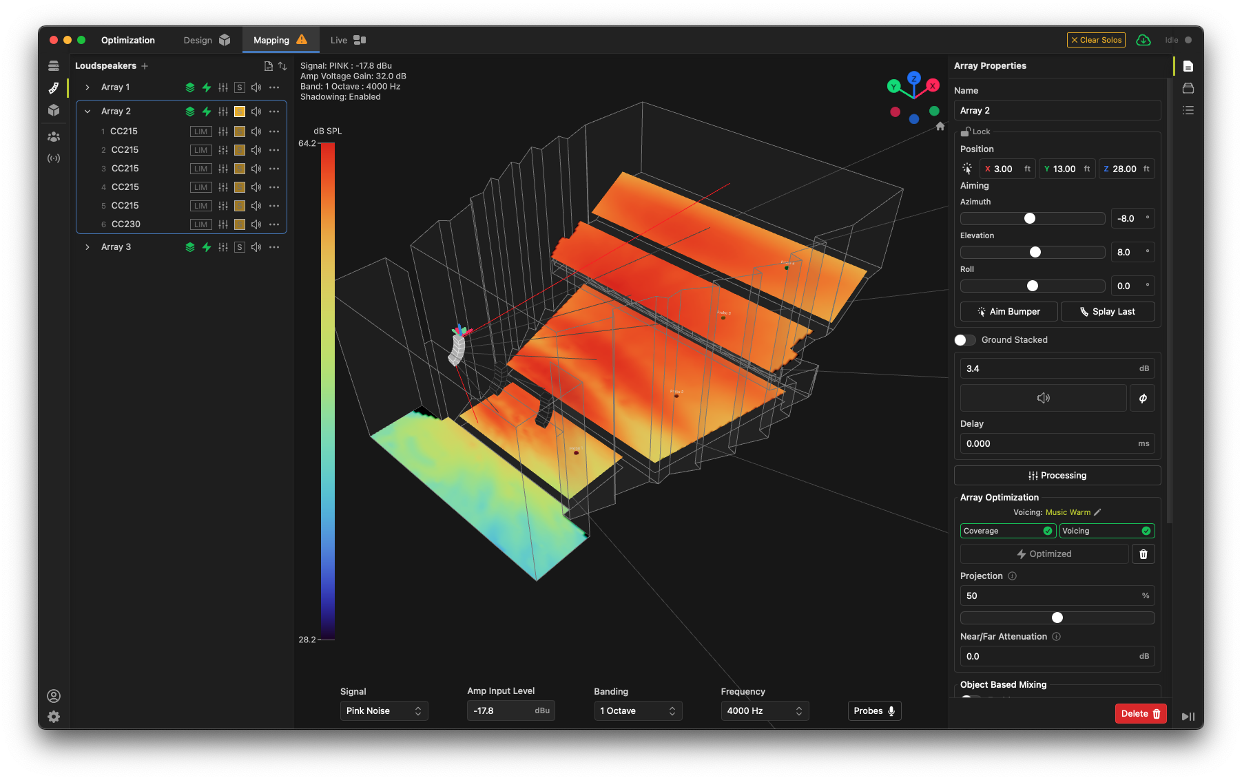
To optimize an array, start with the array properly aimed and aligned into the listening area. It is often best to view this process in the Mapping tab. Ensure that the listening planes are enabled for mapping using the control. Next, select the array in either the 3D view or the Loudspeakers list. You will see the array min/max coverage limits and the principal axis of each array member box in the 3D view.
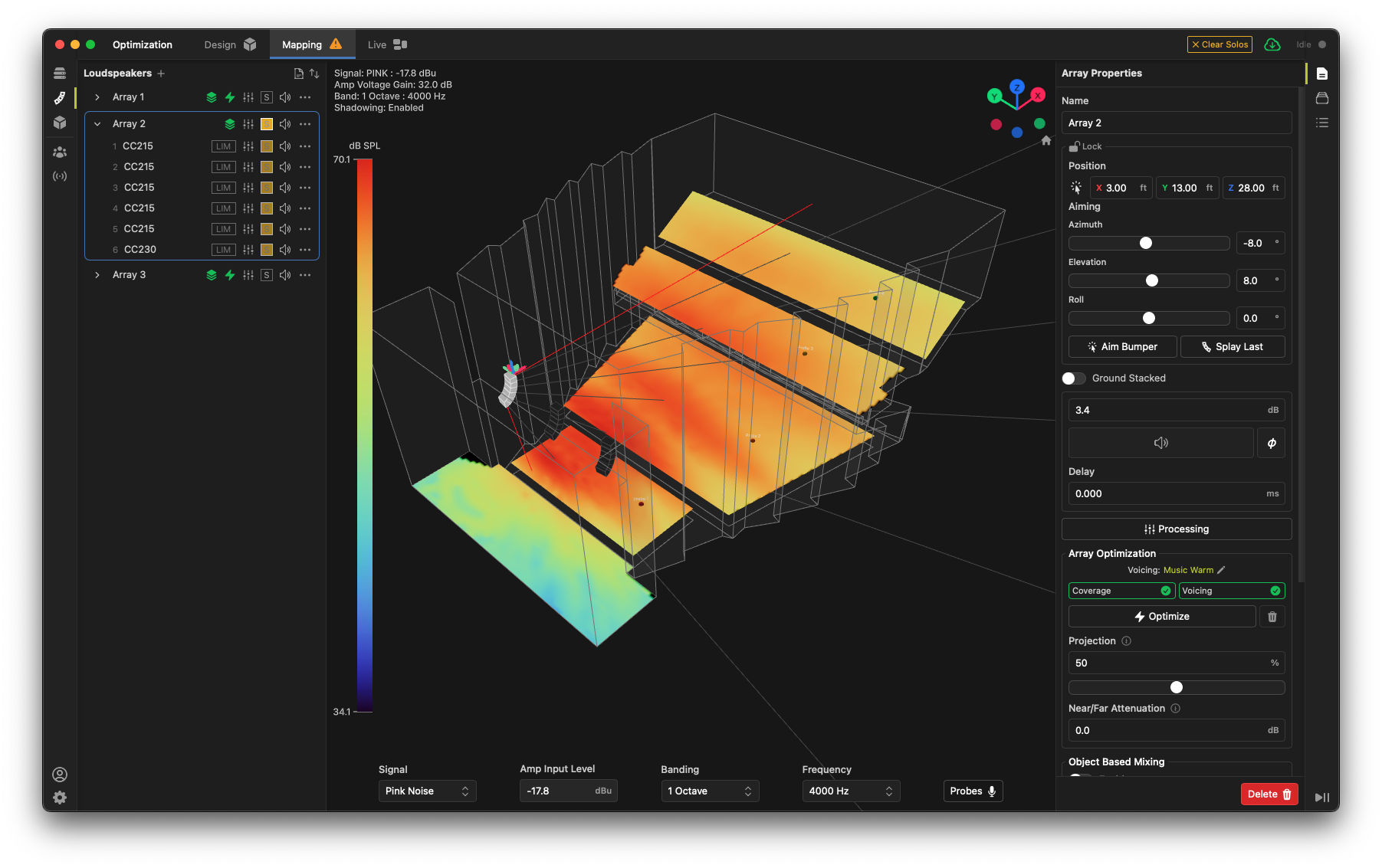
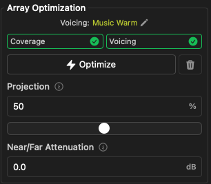
The properties box on the right will now show the Array Optimization controls. These controls are as follows:
-
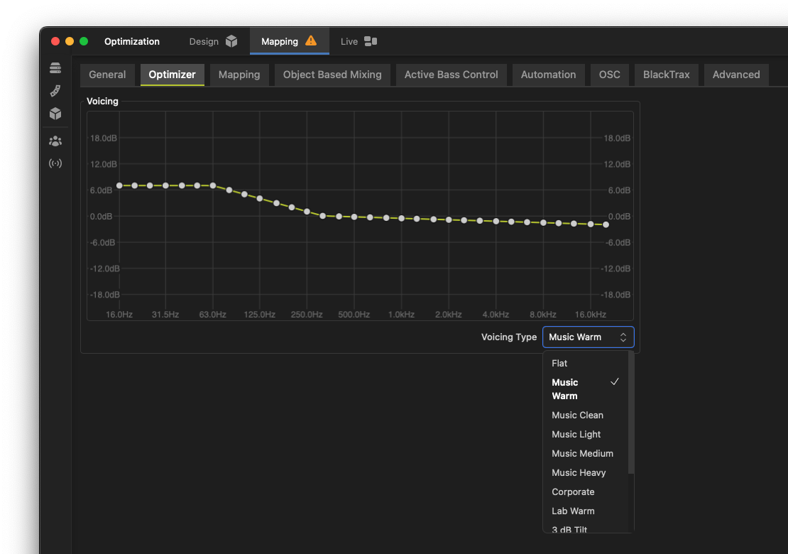
Voicing: Shows the currently selected voicing curve for the overall system. Note that the voicing curves are global to the project. Click the pencil icon to select a new voicing curve or create a custom voicing. Default: Music Warm.
-
Coverage and Voicing checkboxes: Select which optimization functions you wish to perform. You may choose either or both. Default: Both selected.
-
Optimize button: Click this button to start the optimization process. The optimization will run for a few moments, then the results will be applied to the array and shown in the 3D view and mapping tab. If the array is connected to Driveflex amplifiers, the results will be automatically synchronized to the amplifiers.
-
Reset button: Click this button to reset the array to its original state before optimization.
-
Projection: Sets the weighting of the listening area for the optimization algorithm. Value of 0% means all seats are weighted evenly over distance, while 100% weights seats further from the array more heavily. Default: 50%.
-
Near/Far Attenuation: Sets the desired high-frequency falloff of the array over distance. A value of 0 dB means you prefer no high-frequency attenuation over distance, while 6 dB means a 6 dB reduction in high frequencies at the furthest point in the listening area. We recommend higher values for more extreme coverage areas. Default: 3 dB.
If you wish to edit the voicing, click the pencil icon or open the Optimizer tab in the project settings window. You may choose from a variety of preset voicing curves or create your own custom voicing curve. Note that the voicing curve is global to the project, so all arrays will use the same voicing curve. This is to ensure a consistent tonal balance across the entire system.
Once you are satisfied with the optimization settings, click the Optimize button to start the optimization process. The optimization will run for a few moments, then the results will be applied to the array and shown in the 3D view and mapping tab. If the array is connected to Driveflex amplifiers, the results will be automatically synchronized to the amplifiers.
Exporting data
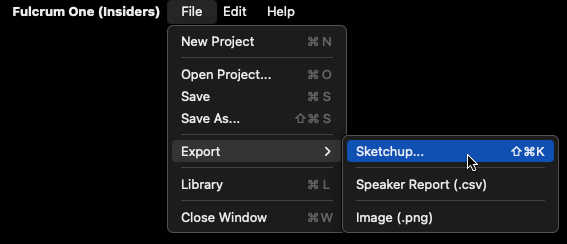
Data can be exported from Fulcrum One in various formats to help translate your designs into other programs for display and documentation or to include data in BIM models or drawing packages. Available export formats are present in the File -> Export submenu.
Sketchup
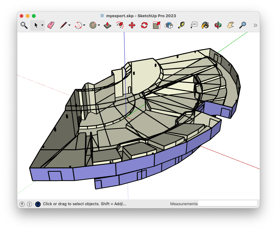
The current 3D world, including all placed modeling objects and loudspeakers can be exported into the Sketchup file format ".skp" using the Export -> Sketchup option. The system design can then be used in external drawing and documentation programs or included in BIM models. Measurement units are embedded and compliant with Sketchup standards such that files will open properly scaled inside the Sketchup application.
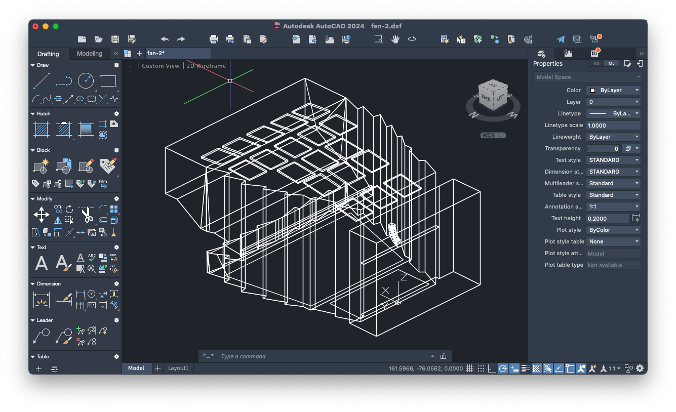
DXF
Identically to the Sketchup exporter, the current 3D world may also be exported into the DXF file format ".dxf" using the Export -> Drawing Exchange Format option. While DXF files are inherently "unitless", One produces data scaled to the following measurement standards depending on the selected Units in the global program settings for One:
| Selected global units in Fulcrum One | Exported DXF file measurement unit |
|---|---|
| Imperial | Feet |
| Metric | Meters |
Speaker report
The speaker report can be easily exported at any time using the Export -> Speaker Report option. This produces a ".csv" file, identical to that in the Speaker Report window.
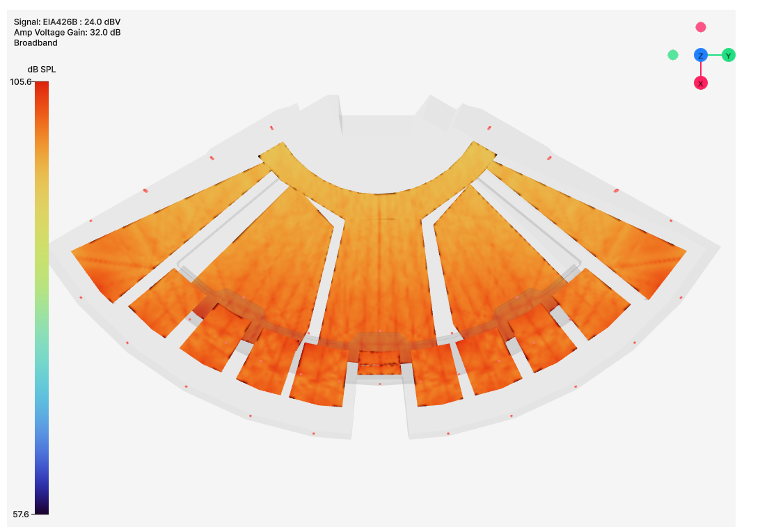
Image
A ".png" image file can be exported of the current model view at any time using the Export -> Image option. This is helpful for creating slides for presentations or reports, allowing you to easily show model or mapping data.